Difference Between Decoder and Demultiplexer
 Decoder and demultiplexer are the combinational logic circuits. The prior difference between decoder and demultiplexer is that the decoder is a device used to decrypt the the input streams from one format into another. On the other hand, the demultiplexer is used to route the information from one input line to any of the multiple output lines. A decoder is considered as a certain case of a demultiplexer.
Furthermore, a decoder is demultiplexer without data input stream, and it contains inputs instead of select lines. Although when enable is used within a decoder circuit it completely resembles demultiplexer.
Content: Decoder Vs Demultiplexer
Comparison Chart
| BASIS FOR COMPARISON | DECODER | DEMULTIPLEXER |
|---|---|---|
| Basic | Logic circuit which decodes an encrypted input stream from one to another format. | Combination circuit which routes a single input signal to one of several output signals. |
| Operations are inverse of | Encoder | Multiplexer |
| Input/Output | n number of input lines 2nnumber of output lines. | n number of select lines 2nnumber of output lines. |
| Application | Detection of bits, data encoding. | Distribution of the data, switching. |
Definition of Decoder
The decoder is a combinational logic circuit whose purpose is to decode the information. It is comprised of n number of input lines and 2n number of output lines. In every probable input condition, among the various output signals, only one output signal will produce the logic one. So, this n-to-2ndecoder can also said to be min-term generator where each output corresponds to precisely one minterm.
Generally, there are 3 types of line decoders are used that are 2-to-4, 3-to-8 and 4-to-16. The decoder is also used in the detection of the particular group of bits (code) at the input side. It can discern one or more n bit combinations with the help of n-to-2n configuration.
What is the need of a decoder?
In computer, instructions are used to inform and order the processor what operation is to perform next. Instructions are in the form of machine language (i.e., 1s and 0s), it needs to be decoded before its execution. So, the processor decodes the instructions before executing it.
Structure of the decoder
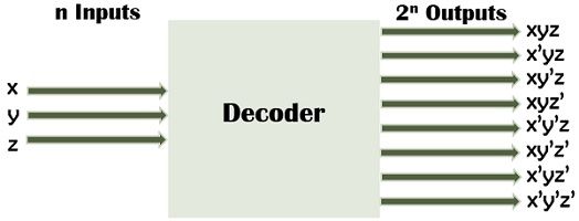 The above-given diagram shows the decoder where according to the condition for three input lines (i.e., n=3) there must be 2n output lines that are 8 output lines. A decoder can produce at most 2n possible minterms with n bit binary code such as for 3 bits the generated outputs can be 000, 001, 010, 100, 110 and 111 (011 and 101 could be unused and don’t care combinations).
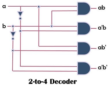 A 2-to-4 decoder with input a and b would contain four AND gates and 2 NOT gate as shown in the diagram. The generated output of the decoder are ab, a’b, ab’ and a’b’, wherein each possible input only one gate could produce “1”(high) as an output.
Definition of Demultiplexer
The demultiplexer is quite similar to the decoder, but it has select lines. It is used to switch single input lines over the multiple lines. In simpler terms, it accepts digital information from one input signal and disseminates it over a given number of output lines. It is comprised of data input line, select lines and output lines.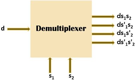
Structure of Demultiplexer
Now, let’s understand the configuration of the basic 1-to-4 DEMUX circuit. So, from the below-given diagram, the data input line is inserted in all of the AND gates. Select lines are intended to make only one gate usable at a time. Therefore, the data visible on the data-input line will only go through the chosen gate to the associated data-output line.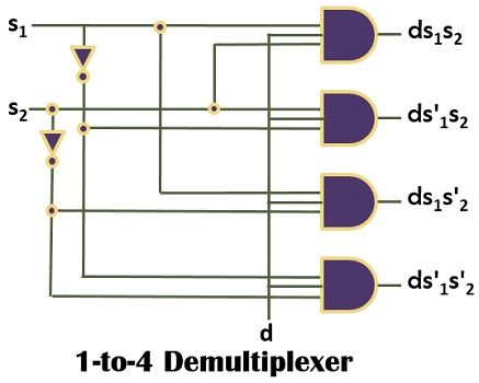
posted by Anidya Kayal @ August 19, 2019
0 Comments
![]()

0 Comments:
Post a Comment
Subscribe to Post Comments [Atom]
<< Home